
Sebastien Lebreton, Principal Applications Engineer at Semtech, has been building and testing devices featuring LoRa® chips for eight years. An expert in the field, he has been working with wireless technologies since 2001, and has regularly been called upon to teach engineers across the LoRa developer ecosystem how to be successful in this arena.
Over the years, I have explained how to test devices with LoRa® chipsets a dozen times or more during seminars, workshops and in informal meetings with customers. The need to write and publish these recommendations for the benefit of the industry has become more than apparent. So, sit back, enjoy a cup of coffee and read on.
Often people come and see us at Semtech, typically electronics manufacturing services (EMS) companies, and ask “what do I need to do to test my devices?” Test engineers are often concerned about the difficulty of conducting such tests. In the end, these are radio frequency devices and the testing is–by nature–more complex than for wired products.
Nevertheless, with proven global adoption of the technology among system integrators and industrial companies (https://semtech.com/lora/ecosystem), many contract manufacturers (CMs) have started wondering how they can assure that the high-volume products coming out of their assembly lines have been sufficiently tested.
Rest assured, it’s not really that complicated.
It’s a Wireless Device, After All
The LoRa physical layer (PHY) is a low-cost, transceiver device, like many others. If we look at what a typical connected device looks like (focusing on the RF portion) the situation isn’t all that complicated. Take a look at Figure 1:
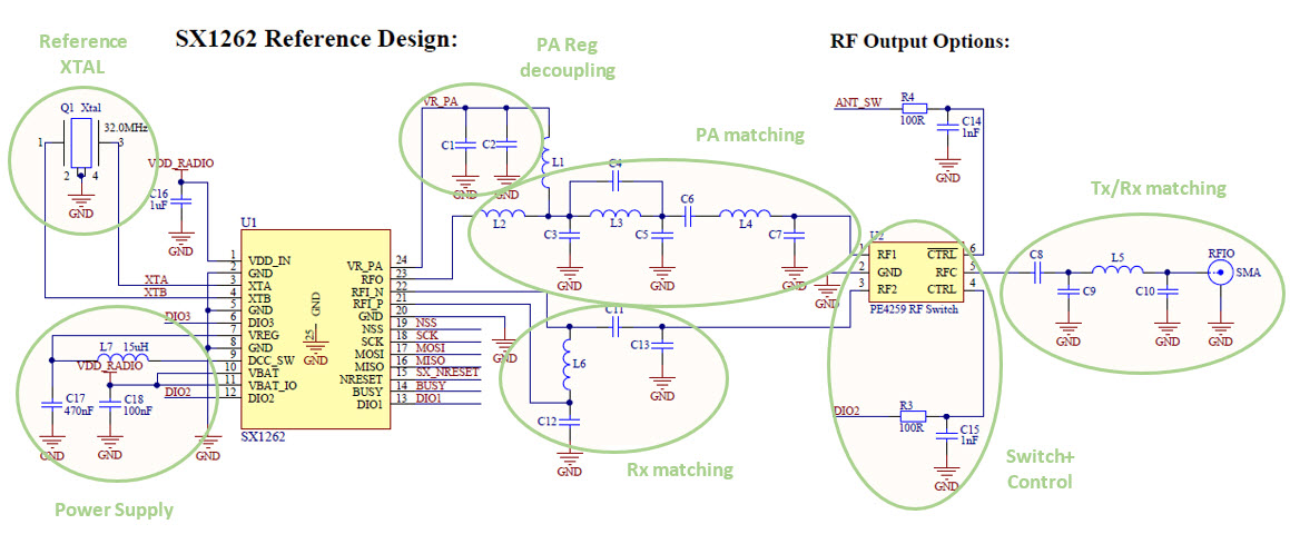 Figure 1: SX1262 Transceiver Reference Design
What you typically see are the following components:
- a power supply
- decoupling capacitors
- a wireless Tx and Rx device (transceiver or TRX for short)
- low-value discrete matching elements, such as pF capacitors and nH inductors
- perhaps an antenna switch
- a time reference
- either a Temperature Controlled Crystal Oscillator (TCXO) or a crystal (XTAL)
- an antenna
Phew! “It’s not that lightweight after all,” you’ll argue with me! “It sounds like you are talking about 30 components. Do you think my client really has the test time available to check all these!?”
Though the list of components may look intimidating, decent test coverage can be obtained with only a few tests. Rest assured, it will not be all that expensive or time-consuming.
Know What You’re Aiming For
The trick here is to really understand the goal of the testing, and not over-engineer the test solution. What are you really trying to achieve? Think of it this way: Semtech delivers devices that are tested and conform to the appropriate device specification. The same is true for the accompanying microcontroller unit (MCU) driving the LoRa chip. Similarly, your timing vendor should have sold you reels of tested crystals (XTALs) or temperature compensated crystal oscillators (TCXOs), and the same holds true for all components on the board. So, you’re really trying to figure out what might have gone wrong during PC board fabrication and assembly. Here are some possibilities:
- There may have been an issue with one or more of the soldering processes, and some of the capacitors, inductors or active devices are misplaced or improperly soldered to their pads.
- There may have been a mistake in the handling/stocking/selection of the reels of the various components. This led to having a 100nF capacitor soldering in-lieu of that super-critical 1.8pF which was needed for antenna matching.
- Perhaps the assembly house used the wrong reel, or there was a mistake of some kind with that XTAL, and now your frequency reference is at 26MHz instead of the specified 32MHz.
- One of the components on the line could possibly have had a grounding defect, causing potential electrostatic discharge (ESD) on the active parts, with Electrical Over Stress (EOS) causing additional leakage current, or even a malfunction of this sensitive RF device. (Typically, the input of very high-performance low noise amplifiers (LNAs) can be more susceptible to ESD, for instance.)
- It’s possible that the stocking guidance provided by the supplier, and adherence to a specific Moisture Sensitivity Level (MSL), wasn’t respected, causing some chips to be physically damaged at the time of reflow soldering at high temperature.
Many other production-related issues may also crop up. Perhaps you have your own ideas of what could possibly go wrong.
It quickly becomes clear that we’re not trying, during a production test, to characterize a device and make sure that every single component is correct and well placed. Instead, we need to think about coming up with the minimum set of simple tests, with the smallest set of equipment available on the test floor, and maximizing the test coverage of that particular device. It may seem impressive and complex but all-in-all, many assembly-related issues can be caught quickly, at low cost.
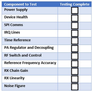
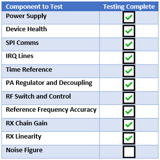
In general, here are the items you should be sure to test:
Table 1: Components to be Tested
Simple Recipes, Good Results
Let’s take the obvious tests out of the way. Time base, switch, soldering of SPI and IRQ lines, RF passives Tx, RF passives Rx, and antenna.
For example, irrespective of how the test controller is built, you’ll need to verify that it can interact with the LoRa IC through its SPI interface. With this simple test, you can assume that the chip is alive and well, with a proper register write / read back, or even a hardware version check. To be even more cautious, you can go ahead and exchange a couple of packets (ping-pong style) with a resident unit on the test floor, responding to any request with a specific format on a given channel. This way, you can make sure that the other IRQ lines you may be using in your application firmware (like preamble detection, Sync Word detection), are indeed well soldered to the companion host MCU. Because it is free, having exchanged a couple of packets with a proper device, you can even presume that your time reference is well soldered, probably fairly close to 32MHz.
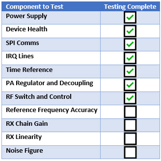
At the end of this testing, the following components will have been verified:

There is still a fair amount to test on this board, such as the assembly of all matching components in Tx and Rx. Let’s focus on Tx first. Here, the idea is to monitor both the intake power (Pin, from the power supply), and the output power (Pout, from the Power Amplifier, at the RF frequency of interest), and ensure that both are reasonable. It will be difficult to be 100 percent sure that all individual capacitors and inductors are correct and properly assembled. However, by monitoring the supply current and the output power (Pin, Pout), those values will deviate sensibly if there was an assembly issue. The same applies to the decoupling caps around the chip, especially the 2.2 nF–47 nF, which are typically used on the “VR_PA” net. When these capacitors are missing or have improper values, the PA regulator (whose output is a DC voltage on VR_PA) is typically unstable. This creates ripple and, therefore, spurious emissions around the carrier, as well as a drop in fundamental power. All of these issues will be caught by an estimation of the overall system efficiency.
Furthermore, if the topology used on the board uses an RF switch to separate the Rx and Tx paths, you also have a verification that:
- The switch is healthy on the Tx path
- Its control lines (from either the host or the LoRa IC itself) are correctly soldered and controlled.
Lastly, this simple test also verifies that the inductor of the buck converter onboard the SX126x and LR111x chip, when applicable, is in good shape. Without it, or with an improper component soldered here, the Tx wouldn’t be functional, or the power intake would be higher than expected.
Components now verified:
Is the Frequency Reference Accurate?
When the device employs a TCXO or any active oscillator, the accuracy of the frequency reference is guaranteed by the supplier. Therefore, verifying that the transceiver can transmit and receive packets is sufficient. In the more common case of an XTAL being used, it is a little more tricky, because half of the oscillator is in the chip (the reactive element with negative resistance), and the other half (the piezo-electric resonator) is outside. On top, the resonance frequency of the XTAL is being tuned by its load capacitance, which may be inside or outside the IC.
There are many techniques to accurately measure the frequency of the reference oscillator. Here is a glimpse of additional options, from the more expensive to the least expensive options:
- The bench is equipped with a spectrum analyzer. In this scenario, it is trivial to request the transmitter to generate a CW tone at, for instance, 915MHz, and measure the resulting carrier with the SA, typically with a Span of 100kHz and a Resolution Bandwidth (RBW) of 1kHz. Given that 1kHz is approximately 1ppm, the accuracy of that measurement will be 1ppm or so, more than enough for communications using LoRa.
- There is a frequency counter on the bench. On some of the Semtech platforms, like the SX127x family, a buffered version of the reference oscillator can be made available on a pin called CLKOUT, with its frequency divided by 2, 4, 8, 16 or 32 (register selectable). The frequency counter will provide an accurate measurement of the reference frequency, with sub-ppm precision. Note: It is not possible to connect a probe to a potential test point on the XTA or XTB nets, between the XTAL and the RF IC; it would load the XOSC by a couple of picofarads (pF). These types of XTALs typically have a pullability of 10ppm/pF, and loading them with as little as 1ppm would bias the result tremendously!
- No test equipment is available, only a companion “golden unit” for packet exchange and power/RSSI estimation are available. The recommendation in this scenario is to rely on multiple packet exchanges with the golden device, whose reference frequency should be very accurate (typically employing a 0.5ppm TCXO). However, you shouldn’t be using LoRa modulation for this data transfer, because LoRa is very forgiving with frequency errors, coping with up to 25 percent of its programmed bandwidth in error. That is, for a LoRa 125kHz communication, the acceptable offset is up to +/-31kHz! This being the case, consider using one of the following methods:
- If the minimum operating bandwidth is quite high (for instance, 125kHz when using the open LoRaWAN® protocol), then run a session with the golden unit with LoRa BW = 31.25kHz. If this works, it means that the frequency accuracy at the temperature of the test (25°C) is better than +/-8kHz (one fourth of the programmed bandwidth). This means that, over temperature and after ageing of the XTAL, the frequency will never be less accurate than +/- 30kHz.
- If the minimum operating bandwidth can be very low, preventing from running an exchange at one fourth of the target bandwidth (that is, anything below LoRa BW = 31kHz), then most probably that device will also use a TCXO (the frequency accuracy requirement will make it difficult to use a cheap XTAL). If it doesn’t, you can always run an FSK ping-pong test at very low bandwidth (a couple of kHz), with the AFC disabled and Fdev set to +/-4kHz at most. With this modulation index, the receiver would only capture packets if the error was less than, approximately, 2kHz (one half of the programmed Fdev). In this case, the initial accuracy at room temperature would be confirmed to be approximately 2ppm.
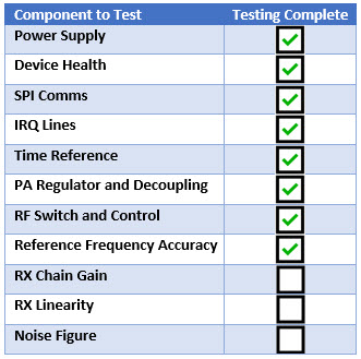
Components now verified:
Understanding Receiver Quality
During the TX tests, the ping-pong exchange with a unit on the test floor, considered Golden, has verified that the LoRa Tx works properly. In fact, all Semtech products are tested individually, to ensure that the LoRa modulator and demodulator inside the chip are correct. However, it can prove very useful to use the LoRa receiver to check the assembly of the Rx chain. Looking at the Rx path (Figure 2), from the antenna to the SPI interface, you can find: antenna, the antenna matching switch (if used) , more Rx matching balun (if the LNA input is differential) , the Semtech receiver including LNA, mixers, and ADC, followed by all the baseband parts like decimators, channel filters, demodulator, packet engine etc. Our goal is to check every part from the antenna to the integrated LNA input.
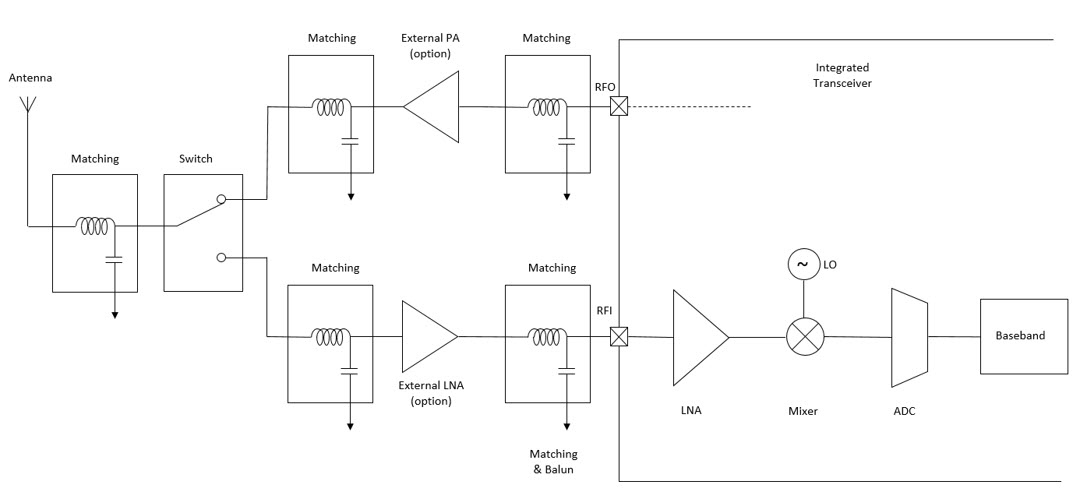
Figure 2: Rx Path
The quality of a receiver is verified by:
- Its sensitivity, which is its ability to receive very low levels of signal
- Its linearity, important for coexistence with out-of-band interferers, and
- Its blocking immunity, the ability of the receiver to work in hostile RF environments
All the components placed between the antenna and the LNA input can influence sensitivity, linearity and blocking immunity. However, in a production test, it is worthless (and not economically feasible) to test these parameters. Doing so would need to happen during the characterization phase, on a small number of prototypes or pre-series. Luckily, a confidence check can be run by estimating the gain and the Noise Figure (NF) of the receiver. These two parameters will help verify that the Rx is healthy, which means that it will be sensitive, linear, and as immune to jammers as it should be.
The most basic and quickest test is to evaluate in-band RSSI. All Semtech LoRa chips support the reading of instantaneous RSSI, so the test is as simple as setting the device in Rx mode, injecting a known, controlled level of RF signal in the channel to the antenna, and verifying that the RSSI reading is within reasonable range of the target (+/-3dB, depending on the signal coupling methodology). Running this quick and simple test verifies that the gain of the receiver is correct; that is, the LNA built into the chip is in good shape (the RF input has not been damaged by EOS at assembly time, for instance), and that all matching/balun/switch elements between the antenna and the chip are correct. This is a great achievement for such a basic test, requires no external equipment, and takes only milliseconds to poll the RSSI values returned by the receiver.
Components now verified:
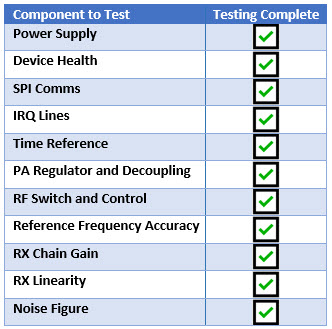
All that remains to test is the receiver Noise Figure. The NF qualifies the ability of the Low Noise Amplifier (LNA) to amplify the wanted signal without degrading the signal-to-noise ratio (SNR). The NF will degrade if the LNA is mismatched. However, a smaller LNA mismatch may not be visible when measuring the receiver gain. Techniques to measure the NF are a little more complex, and certainly out of scope of this paper. In fact, they are made more difficult in the presence of an integrated receiver, where the output of the LNA isn’t accessible for testing. It does not really matter, because these methods will also be more time-consuming, and therefore not well adapted to industrial unit testing, which must be quick in nature.
Using the LoRa Demodulator
This is where our LoRa demodulator becomes very handy. On top of the RSSI we’ve used before, the LoRa demodulator can also estimate the SNR when it has received a proper LoRa packet. The method is to couple to the antenna a known level of signal, send a dozen valid packets over the channel and then give an average of the RSSI/SNR that was observed.
Because LoRa modulation works below the noise floor of the receiver, you should run this test in the region where the level of signal is well below the noise floor, a region where the SNR indicator is fairly linear and can be trusted. A good practice is to run this test at, for instance, SF9 or SF10, where the packets are still short (resulting in a shorter test time), but where the SNR can be as low as -10dB. Set up the resident Tx board sending the packets to couple a fairly low-level of signal to the Rx antenna, so that the SNR indicator returns -10dB on a golden sample. This may require the use of attenuators, since the sensitivity at SF10 is about -130dBm. One technique is to replace the antenna of the Tx with a 50Ohm dissipative load. During that test, it is good to monitor the RSSI of the received packets (and, ideally, to work in an RF-shielded environment, such as a Faraday cage). The purpose of monitoring the RSSI is to ensure that you really are measuring the thermal noise floor of the receiver (a consequence of the NF we’re trying to estimate), and not potential interferers that may show up in the channel (for instance, if many other devices are being tested at the same time on the test floor).
Because this measurement is sensitive, I would also recommend doing a QA sampling on each batch, and measuring the sensitivity of a couple of devices with calibrated test and measurement (T&M) equipment. This will allow you to have more confidence and more precision with regard to the Noise Figure estimation.
Components now verified:
Most T&M equipment manufacturers have added LoRa capability to their product portfolio. For example Rohde & Schwarz, LitePoint, Anritsu, and Keysight propose LoRa personalities for their offer of Arbitrary Waveform Signal Generators.
In Summary
It can be very quick and cost effective to run a production test on devices with LoRa ICs, with very simple tools and a good methodology. The test harness can be as simple as a golden reference installed on the test floor, with known and trusted RF characteristics such as output power level, a good positioner, and a Faraday cage with high-quality distributed attenuators to be able to inject the proper level of signal.
With simple tools and this simple guidance, you can find many issues without spending a lot of time or money.
Semtech, the Semtech logo and LoRa® are registered trademarks or service marks of Semtech Corporation or its affiliates.
