LoRa® Corecell Reference Design for Full Duplex Gateway Applications
The LoRa® Corecell Full-Duplex gateway reference design (SX1302CFD915W1-X and SX1302CFD490GW1) is a highly integrated indoor and outdoor gateway solution designed for applications requiring intense downlink activities in the U.S. 915MHz ISM band or China 490MHz band.
Unlike typical half-duplex designs, a full-duplex gateway allows simultaneous transmission and reception of LoRa packets through the use of frequency filtering. This drastically reduces latency by eliminating the need for uplink traffic to be gated by downlink traffic, and vice versa. For example, it improves the response time of LoRaWAN® protocol messages for applications that require fast, systematic acknowledgement. It is also suitable for large file downloads such as Firmware Updates Over-The-Air (FUOTA) while processing uplink traffic, reducing time and cost of managing end-devices.
The LoRa Corecell Full Duplex Gateway is not suitable for the EU868 band since uplink and downlink messages do not have frequency separation; they are transmitted on the same channel. Secondly, there are few high-traffic applications for LoRaWAN EU868, which specifies a 1% duty cycle limit.
Key Features and Benefits
- Supports Full Duplex LoRa Operation
- 8-Channel Uplink and 1 Channel Downlink
- Operates in the US915 or CN490 LoRa Bands
- Provides all of the advanced capabilities of the LoRa Core ™ SX1302
-
- 64x LoRa packet detectors
- 16x 125kHz LoRa demodulators for SF5 to SF12 and SF5 to SF10
- 1x 125/250/500kHz Single SF LoRa demodulator
- 1x (G)FSK demodulator
- 1x Listen-Before-Talk SX1261 receiver
- 10x power reduction compared to the previous generation of LoRa baseband
- Transmit output at antenna up to +27dBm
- Receive sensitivity at antenna down to -140.8dBm at SF12, 125kHz BW for US915
1. Architecture
From a hardware perspective, the LoRa® Corecell Reference Design for Full Duplex Gateway Applications (hereafter LoRa Corecell Full Duplex Gateway) consists of three major blocks: LoRa Corecell board, duplexer, and Raspberry Pi. The block diagram is shown in Figure 1.
Based on the SX1302 and SX1255/7 platforms, the LoRa Corecell board is designed to simultaneously support 8 uplink channels and one downlink channel (Figure 2). Thanks to the advanced design of the SX1302 baseband IC, the uplink channels can detect up to 64 different LoRa packets and simultaneously demodulate 16 125kHz LoRa packets with spreading factors between SF5 and SF12. It is also equipped with one 125/250/500kHz demodulator for single SF operation, and one (G)FSK demodulator for legacy applications. A SX1261 is present to enable Listen-Before-Talk. In addition to its demodulation capability, the SX1302 also offers significant power consumption and cost reduction when compared to the previous generation of LoRa baseband ICs.
In addition to the external duplexer, the SX1255/7 is the other major enabler for the full-duplex capability of this reference design. The SX1255/7 is a highly integrated RF transceiver that is equipped with two independent synthesizers, thus enabling the receiver and transmitter to be tuned to two different frequencies. Each SX1255/7 is tuned to capture 1MHz (on up to five channels) of the RF spectrum, with TX frequencies ranging within the LoRa uplink band and RX frequencies in the downlink band.
And, with the help of a discrete high performance power amplifier and low noise amplifier, the output power at the antenna port can be as high as +27dBm, and the receive sensitivity can be as low as -140.8 dBm for US915 and -137.4 dBm for CN490.
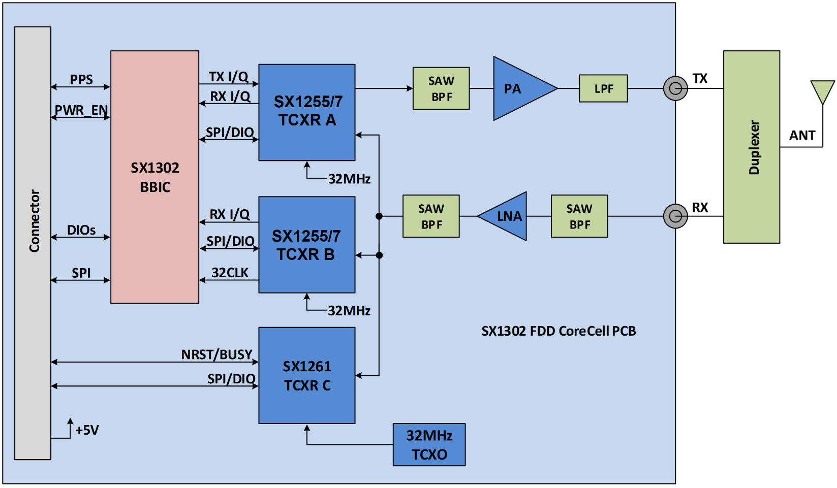
Figure 1. Block Diagram of the SX1302 LoRa® Corecell Full-Duplex Gateway Reference Design
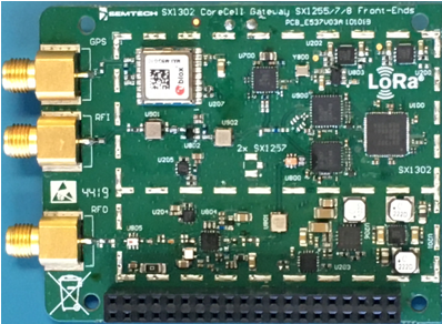
Figure 2: SX1302 and SX1257 Corecell Board
The primary function of the duplexer on this reference design is to isolate/protect the sensitive receiver front end from being desensitized by the much more powerful signal that is being broadcast by the transmitter. There are many types of duplexers available out in the market, such as cavity, ceramic, surface acoustic wave (SAW), etc. Cavity duplexers are generally larger in size and higher in cost, but probably offer the best performance. Ceramic duplexers are usually much less expensive, with acceptable performance and a smaller size. Lastly, SAW duplexers are the smallest and typically the least expensive. However, their power handling capability and performance are generally at the lowest level. As an effort to maintain flexibility, we’ve intentionally kept the duplexer board separate from the LoRa Corecell board. For outdoor applications, the cavity duplexer was chosen for its performance capabilities. For indoor applications, where cost generally outweighs performance, a ceramic duplexer was chosen.
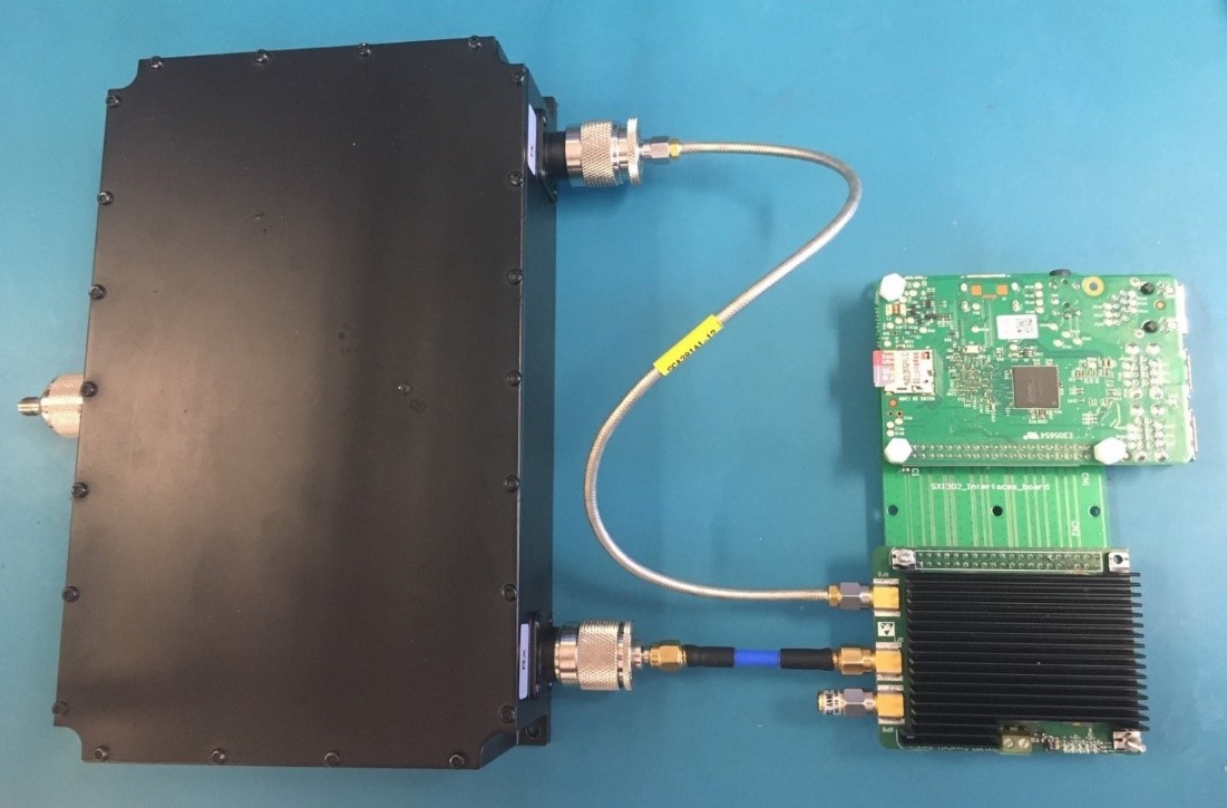
Figure 3. Complete US915 reference design with cavity duplexer
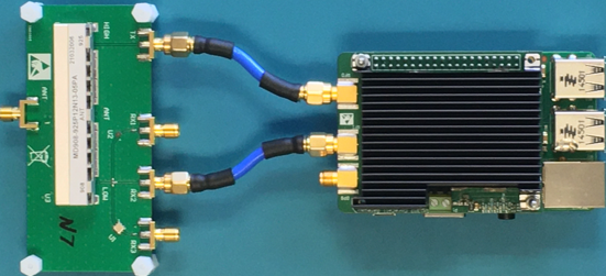
Figure 4. Complete US915 reference design with ceramic duplexer
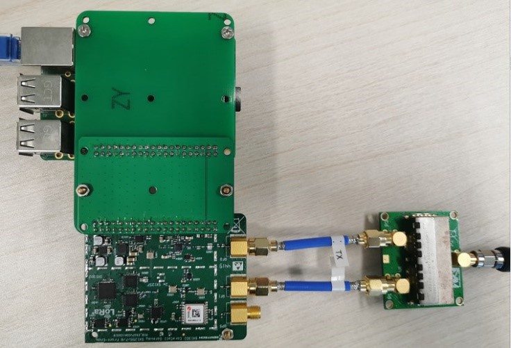
Figure 5. Complete CN490 reference design with ceramic duplexer
Table 1. Duplexer Specifications
|
|
|
Fudian Ceramic |
Rising HF Cavity |
Fudian Ceramic
|
|
||||||
|
908-925-C128-20210308 |
WEXDUP900-13-203 |
CMD810C505-480P10-20A |
|
||||||||
|
MIN |
TYP |
MAX |
MIN |
TYP |
MAX |
MIN |
TYP |
MAX |
UNIT |
||
|
ANT-RX |
Passband |
||||||||||
|
Frequency Range |
902 - 915 |
902 - 915 |
470 - 490 |
MHz |
|||||||
|
Insertion Loss |
|
|
5.0 |
|
|
2.5 |
1.0 |
|
3.0 |
|
|
|
RX VSWR |
|
|
2.0 |
|
|
1.3 |
|
|
1.5 |
|
|
|
ANT VSWR |
|
|
2.0 |
|
|
1.3 |
|
|
|
|
|
|
Out of Band, Attenuation |
|||||||||||
|
Low Frequency |
30 |
90 |
Not available |
dB |
|||||||
|
Near-Band |
35 |
90 |
20-50 |
dB |
|||||||
|
Downlink Band |
25 |
80 |
50 |
dB |
|||||||
|
Downlink Band |
35 |
80 |
50 |
dB |
|||||||
|
TX-ANT |
Passband |
||||||||||
|
Frequency Range |
923 - 928 |
923 - 928 |
500 - 510 |
MHz |
|||||||
|
Insertion Loss |
|
|
5.0 |
|
|
2.5 |
1.0 |
|
3.0 |
dB |
|
|
TX VSWR |
|
|
2.0 |
|
|
1.3 |
|
|
1.5 |
|
|
|
ANT VSWR |
|
|
2.0 |
|
|
1.3 |
|
|
|
|
|
|
Out of Band, Attenuation |
|||||||||||
|
Low Frequency |
30 |
80 |
Not available |
dB |
|||||||
|
Uplink Band |
50 |
70 |
50 (470-490MHz) |
dB |
|||||||
|
2nd and 3rd Harmonic |
(1.5-2.8GHz) |
80 |
Not available |
dB |
|||||||
|
High Frequency |
(2.8-6.0GHz) |
80 |
Not available (1.6-3.2GHz) |
dB |
|||||||
|
TX-RX |
Tx to Rx Isolation |
||||||||||
|
Uplink Band |
50 |
|
|
80 |
|
|
50 |
|
|
dB |
|
|
Downlink Band |
50 |
|
|
80 |
|
|
50 |
|
|
dB |
|
|
POWER |
CW @Tx IN |
|
|
1 |
|
|
50 |
|
|
5 |
W |
|
SIZE |
|
63 x 13.9 x 10.8 |
212.6 x 134.6 x 48 |
Not available |
mm |
||||||
|
TEMP |
|
-40 to +85 |
-20 to +65 |
Not available |
°C |
||||||
2. US915 Performance Summary
The following are the performance data of the LoRa Corecell Full Duplexer Gateway using the cavity duplexer as shown in Figure 3.
All of the transmit measurements were done at POUT at Antenna = +27dBm, bandwidth = 500kHz, and 25 degrees Celsius, unless otherwise stated.
Table 2. Transmitter Modulation Bandwidth
|
SF |
923.3MHz |
925.1MHz |
927.5MHz |
Unit |
|
7 |
555 |
553.5 |
558 |
kHz |
|
10 |
579 |
577.5 |
580.5 |
|
|
12 |
583.5 |
583.5 |
586.5 |
The results shown in Table 2 comply with the Federal Communications Commission (FCC) requirement (Chapter 15.247(a)(2)) that 6dB bandwidth of the transmitted signal shall be at least 500kHz for supported spreading factors, SF7-SF12.
Table 3. Margin in Out-of-Band Emissions in the Non-Restricted Band (927.5MHz)
|
|
SF 5 |
SF 7 |
SF 10 |
SF 12 |
Unit |
|
Normal IQ |
13.6 |
12.6 |
16.5 |
16.3 |
dB |
|
Inverted IQ |
18.5 |
17.4 |
18.2 |
16.4 |
The results shown in Table 3 illustrate the out-of-band emissions in the non-restricted band are greater than 30dB below the reference emission level, and hence comply with the specified requirements in paragraph 15.247(d) of the FCC regulations.
Chapter 15.247(e) of the FCC regulations requires that the power spectral density shall not be greater than +8dBm in any 3kHz band during any time interval of continuous transmission.
Table 4. Maximum Transmit Power Spectral Density
|
SF |
923.3MHz |
925.1MHz |
927.5MHz |
Unit |
|
7 |
7.7 |
7.5 |
8.0 |
dBm/3kHz |
|
10 |
5.1 |
5.0 |
5.3 |
|
|
12 |
4.8 |
4.7 |
5.1 |
The results shown in Table 4 illustrate that the maximum power spectral density complies with the +8dBm/3kHz limit as specified by the FCC regulations.
Table 5. Margin in Spurious Emissions for SF7-SF12
|
Frequency |
Margin from Limits |
Unit |
|
|
Restricted Band |
Non-Restricted Band |
||
|
Below 1GHz |
13.9 |
60.6 |
dB |
|
Above 1GHz |
17.4 |
47.2 |
|
The results shown in Table 5 illustrate compliance with the spurious emissions limits as specified in paragraphs 15.209(a) for restricted emission limits specified, and in 15.247(d) for non-restricted limits specified in the FCC regulations.
All sensitivity measurements are based on Radio 0, carrier frequency = 908.5MHz, bandwidth = 125kHz, PER = 10 percent, and temperature = 25 degrees Celsius, unless otherwise stated.
Table 6. Sensitivity vs SF
|
SF |
Sensitivity (dBm) |
Delta (dB) |
|
|
Half Duplex |
Full Duplex |
||
|
5 |
-119.7 |
-118.9 |
0.8 |
|
6 |
-122.3 |
-121.8 |
0.5 |
|
7 |
-125.1 |
-124.2 |
0.9 |
|
8 |
-129.4 |
-129.1 |
0.3 |
|
9 |
-132.6 |
-132.2 |
0.4 |
|
10 |
-135.7 |
-135.3 |
0.4 |
|
11 |
-138.4 |
-138.1 |
0.3 |
|
12 |
-141.1 |
-140.8 |
0.3 |
Table 7. Sensitivity Level vs Multi SF Channel (SF7)
|
Frequency (MHz) |
Radio |
Sensitivity (dBm) |
Delta (dB) |
|
|
Half Duplex |
Full Duplex |
|||
|
902.3 |
0 |
-124.4 |
-124.3 |
0.1 |
|
1 |
-123.6 |
-123.5 |
0.1 |
|
|
908.5 |
0 |
-124.8 |
-124.3 |
0.5 |
|
1 |
-123.8 |
-124.1 |
-0.3 |
|
|
914.9 |
0 |
-125.1 |
-124.4 |
0.7 |
|
1 |
-125.0 |
-123.8 |
1.2 |
|
Table 8. Sensitivity Level vs Single SF Channel (SF8)
|
Frequency (MHz) |
Radio |
Sensitivity (dBm) |
Delta (dB) |
|
|
Half Duplex |
Full Duplex |
|||
|
903.0 |
0 |
-123.9 |
-123.7 |
0.2 |
|
1 |
-123.9 |
-123.8 |
0.1 |
|
|
907.8 |
0 |
-124.9 |
-124.3 |
0.6 |
|
1 |
-124.8 |
-124.6 |
0.2 |
|
|
914.2 |
0 |
-124.1 |
-123.2 |
0.9 |
|
1 |
-124.1 |
-123.8 |
0.3 |
|
3. CN490 Performance Summary
The following are the performance data of the LoRa Corecell Full Duplexer Gateway using the cavity duplexer as shown in Figure 3.
All of the transmit measurements were done at POUT at Antenna = +17dBm, bandwidth = 125kHz, and 25 degrees Celsius, unless otherwise stated.
Table 9. Transmitter Occupied Bandwidth Bandwidth
|
SF |
500.3MHz |
505.1MHz |
MHz |
Unit |
|
7 |
118.3 |
118.5 |
118.4 |
kHz |
The results shown in Table 2 comply with the China SRD requirement (part 1.3) that the Operating Channel bandwidth in which 99% of the total transmitted power falls within shall be within the 200 kHz channel width, tested for SF7.
The out-of-band emissions in the non-restricted band are below the required emission level, and hence comply with the China SRD requirements.
The spurious emissions are in compliance with the spurious emissions limits as specified in State Radio Regulation of China, 2019, No.52. part 1.3. We observe no sub-GHz spurious emissions over -65 dBm and no spurious emissions over -50 dBm up to the tenth harmonic.
All sensitivity measurements are based on Radio 1, carrier frequency = 486.9MHz, bandwidth = 125kHz, PER = 10 percent, and temperature = 25°C, unless otherwise stated. While the receiver is active, Radio 0 is transmitting long packets.
Table 10. Full Duplex Sensitivity vs SF
|
SF |
Sensitivity (dBm) |
|
Full Duplex |
|
|
5 |
-115.5 |
|
6 |
-118.1 |
|
7 |
-119.6 |
|
8 |
-124.5 |
|
9 |
-128.0 |
|
10 |
-132.2 |
|
11 |
-135.3 |
|
12 |
-137.4 |
Table 11. Sensitivity Level vs (Multi SF Ch. SF7 & Single SF Ch. SF8)
|
Frequency (MHz) |
Radio |
Sensitivity (dBm) |
|
Full Duplex |
||
|
472.7 |
0 |
-126.9 |
|
473.5 |
0 |
-125.0 |
|
486.7 |
1 |
-121.8 |
|
487.1 |
1 |
-121.9 |
|
497.3 (SingleSF) |
1 |
-124.5 |
4. Availability
The reference designs are known by the following product numbers:
- SX1302CFD915GW1-L : US915 with low-cost duplexer option
- SX1302CFD915GW1-H : US915 with high-performance duplexer option
- SX1302CFD490GW1 : CN490 with duplexer
These products are not available for purchase. Production files are available on the product page. Contact Semtech support if you are interested in a sample. For technical reasons described in the introduction, an EU868 design was not made.
One known limitation not characterized in this document is higher current consumption at +27 dBm TX output compared to the rest of the CoreCell product line. This reference design is for externally supplied power, not powered by battery. Other known limitations are small margin for PSD at SF 7 as shown in Table 4, and I/Q Calibration failures below +19 dBm TX power in some samples. Similarly, we suspect improved performance may be possible with an alternate BOM with RF matching improvements. In general, the BOM of our reference designs are considered placeholder values, and the provided firmware does not represent fully-optimized operation.
5. Resources
5.1. SOFTWARE/FIRMWARE PACKAGES
The HAL and packet forwarder for this reference design can be found at:
https://github.com/Lora-net/sx1302_hal/tree/master-fdd-us915
5.2. DESIGN PACKAGE
Download the Altium design package and production files here.
5.3. ADDITIONAL RESOURCES
LoRa Core SX1302 Homepage - https://www.semtech.com/products/wireless-rf/lora-core/sx1302
LoRa® Corecell Reference Design for Full Duplex Gateway Applications for U.S. 915MHz - https://www.semtech.com/products/wireless-rf/lora-core/sx1302cfd915gw1h
LoRa® Corecell Reference Design for Full Duplex Gateway Applications for China 490MHz - https://www.semtech.com/products/wireless-rf/lora-core/sx1302cfdxxxgw1
Semtech, the Semtech logo and LoRa® are registered trademarks or service marks, and LoRa Core™ is a trademark or service mark of Semtech Corporation or its affiliates.